A typical split load board layout
In order to layout the software as per the photograph follow these steps:

Step 1
Click Edit board and set the number of circuits to 16 (this is total number of available ways for the DB)

Note: We are not including the main switch as an available way, this can be included in the Edit board section as shown in the image below


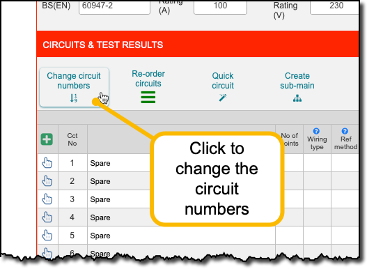
Step 2
Set the circuit numbers to represent the DB layout

Step 3
Enter circuit details as per the board layout

This shows which RCD protects which circuits (the colour coding is for reference only)
RCD Test results
